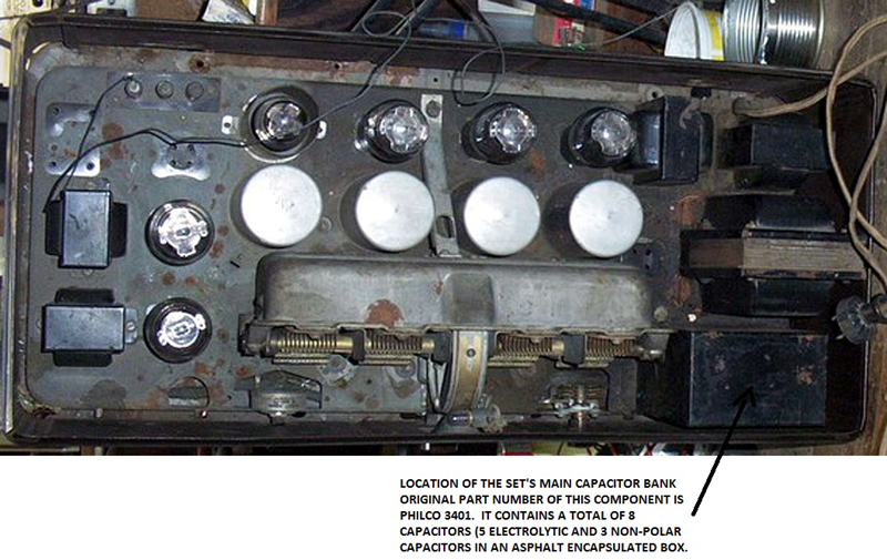
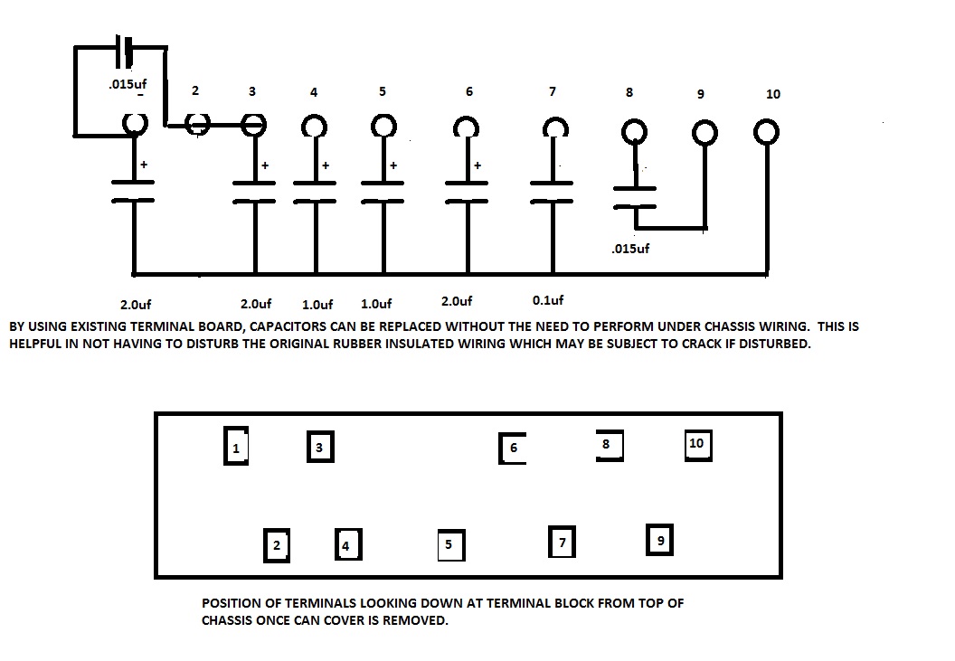
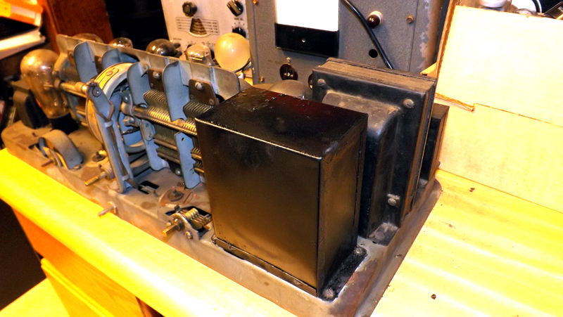
Replacing the capacitors in a Philco Model 87 Receiver chassis should not be a daunting task for the restorer. Most of the set's fixed capacitors are located in the rectangular metal can directly behind the set's power transformer as shown above. The original capacitor bank is sealed in asphalt. It is therefore necessary to remote the original can top, cut the wires leading to the terminal board which forms the bottom of the can assembly, and then replace the capacitors from the top of the chassis. In performing the work in this manner, the under chassis wiring need not be disturbed or cut. The can is mounted to the chassis with four machine screws which are threaded into tapped holes in the chassis.
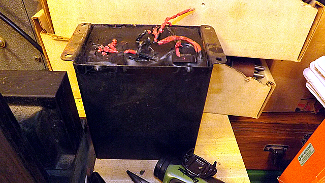
In removing the can cover, it is important not to distort or break the terminal board. We found that once the four mounting screws were removed, the cover could be separated from the base and lifted with a small wedge so that a miniature cutting pliers could be inserted between the cover and the base in order to clip the wires leading up into the asphalt encapsulated portion of the assembly.
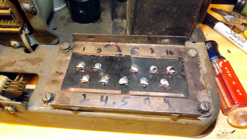
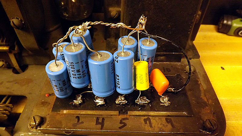
Once the eight new capacitors are soldered in place, the original cover can be cleaned out and reused. Care must be exercised in this process to prevent fires and burns, however it is a relatively simple process. The can should be taken outdoors and placed on a fireproof surface. It can then be heated from the outside with a small propane torch. Be careful not to overheat the metal can because this can cause distortion of the metal. Once the asphalt is liquid, the entire contents of the can, including the old capacitors, can be removed and the can cleaned out, painted and reinstalled as a cover for the new capacitors.
After the completed recapping project, the chassis appears as it did originally.
Once the wiring is completed and checked, the original cover assembly can be stripped of the old parts and asphalt, and then cleaned and painted. While it is not absolutely necessary, it is a good practice to install fiber electrical insulating board around the new capacitors so that they can not come into contact with the sides of the metal can cover.
This completes the procedure for recapping the Philco Model 87 chassis. It should be noted that while this article deals with the restoration of the Museum Of Yesterday's Philco Model 87, Philco used this same type of capacitor enclosure on several of their early AC radios from this era, so this information may apply to other sets as well as the Model 87.