A LOW POWER A.M. BROADCAST BAND TRANSMITTER FOR THE OLD RADIO COLLECTOR
By John DeMajo, K5HTZ
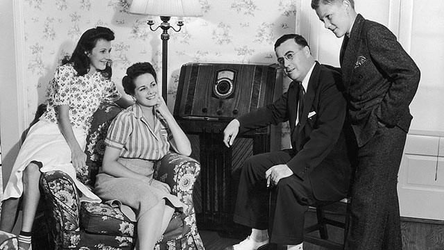 |
As a collector and restorer of old radios, I like to show off my collection by having an actual "old-time" radio show playing through any vintage set that I demonstrate. It not only provides a nice effect, but it is an excellent way to show off the quality of sound that we actually heard on those old pre Hi-Fi Era sets back in the 1940s. There are several options on the market today in the form of solid-state kits and devices of varying degrees of complexity to accomplish this. The SSTran AMT3000, for example, is a well designed little solid-state AM broadcaster. There are also some tube type wireless broadcasters available, such as the one offered, in kit form, by Antique Radio Supply of Tempe, AZ. Wireless broadcasters are not a new concept. As far back as the 1930s, Philco offered a wireless oscillator that was designed to accept the input of a crystal phono cartridge, allowing a stand-alone phonograph turntable to be played through any AM radio without the need to modify the radio chassis to accept an external audio input. Later, Allied Radio Corporation and Lafayette Radio both offered "hot chassis" type 3 tube wireless AM transmitters to the hobbyist. |
A while back, in response to requests I had received through the Museum Of Yesterday web site, I designed a breadboard style, tube based wireless broadcaster which could be built with currently obtainable parts. The device used a 6V6 GT as a tuned oscillator, and a second 6V6 GT as a screen grid modulator stage. The device worked fairly well, aside from the inherent tendency to drift when it warmed up. It also required an external speech amplifier to drive the screen grid modulator. Some readers who had built the device from my plans, commented that there was also a tendency for oscillations or feedback. This was due to the breadboard design which allowed stray RF to go back into the audio stage.
In an attempt to come up with an improved design, I decided to depart from the tuned oscillator concept, and to design Version 2.0 as a crystal controlled AM transmitter, complete with all audio processing circuits included on the single chassis. In most US cities, the 1000 Khz slot on the AM dial is not being used by local stations, so settling on that frequency pretty much assured that a single crystal could serve as the main frequency control in almost any locality.
The photo at left is the original Version 1.0 transmitter, which employed breadboard design
A WORD OF CAUTION: all of these projects utilize voltages in excess of 300 volts AC and DC.
Also of concern on the original verision was the fact that the frame and stator of the antenna coupling capacitor were at full B+ potential. The user therefore had to be warned not to contact or short this component as dangerous voltages were present when the transmitter was in operation.
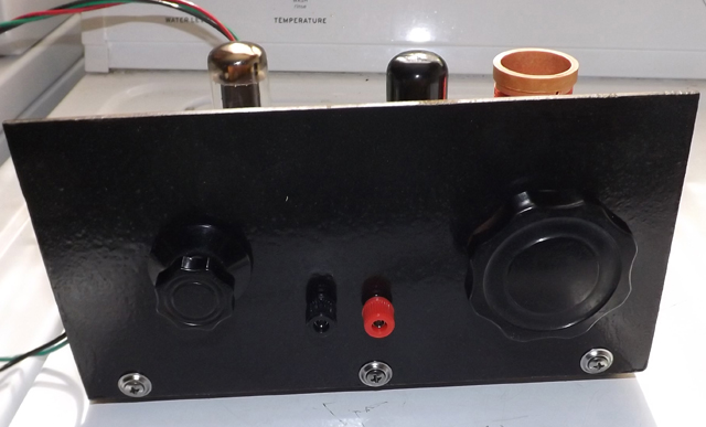
Contrast this to the Version 2.0, which is neatly self-contained on a 10x6x4 aluminum chassis. The updated transmitter employs a crystal oscillator along with a Pi Network type output coupler, which permits connection of either a long wire antenna (may not be legal to use this type of antenna) or a capacitively couplesd power line RF feed such as was used with locally distributed power line radio stations deployed on college campuses before the advent of streaming audio on IP technology.
When I was in school, I had been asked to design a similar device, which was intended to be used as a power line carrier radio station for the campus radio station that was just being formed. Using a similar design, we were able to transmit the signal to all of the buildings on a small college campus, since one main substation was used for the entire physical plant. Power line carrier signals will not cross the windings of a transformer, so they are limited to use in single buildings, or buildings where one transformer or bank of transformers feeds the entire complex.
Here is the schematic of the Version 2.0 transmitter. If you click on the photo at left, you will be able to see and download a larger, printable version of the transmitter schematic.
All of the parts used in this project are currently obtainable from present day commercial suppliers.
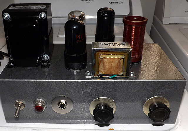
The 1000Khz crystals were used in analog color television receivers, so they are still available through most major electronics suppliers. The transformers, 6V6 tubes, capacitors, resistors, tuning capacitors and chokes are all available from Antique Radio Supply in Tempe, AZ. The aluminum chassis is available from Allied Radio in Chicago. To emulate the look of a 1950s "kit built" style transmitter, we applied a hammertone metallic paint that is readily available in most hardware stores.

Under-chassis view of the transmitter. Click on above photo to see enlarged version
Note that while this device was designed to be used in conjunction with a power-line distributed, low power AM broadcast system, it can be easily modified for use as a low power amateur radio transmitter offering screen grid modulated audio capabilities. By simply replacing the plug in coil and the crystal, with components of the correct frequency and resonance, the transmitter will operate as a screen grid modulated AM phone transmitter on the 160-20 meter amateur frequencies. Information is given below to aid in the design of output tank coils for additional frequencies..
COIL WINDING DETAILS
The oscillator coils used in this project are based on the five-pin coils that are still obtainable from a number of Internet marketing suppliers. A simple Goggle search of 5 pin plug-in coil forms, or such, will usually yield the names of suppliers. Our coil form was obtained from Frank Pellicano at email address frankpellicano@yahoo.com. Frank manufactures these coil forms himself, and he has assured us that they will be available in the future.
| Here is a table indicating the number of turns of wire needed to make tank coils for the desired frequencies. Wire size recommendation is specified below. Single-strand enamel insulated copper wire is recommended. | ||
Frequency Range with 365 uuf tuning capacitor |
Main winding |
Value of windings in uH |
| 150 Khz to 550 Khz | 200 turns #30 overlapping |
1525 uH / 55uH |
| 540 Khz to 1.9 Mhz | 100 turns close-wound #28 |
150 uH primary |
| 1.7 Mhz to 4.1 Mhz | 44 turns #24 close wound |
50 uH |
3.0 Mhz to 7.5 Mhz |
24 turns #20 |
17 uH |
| Note: coils are wound on 5 pin polystyrene forms having an outside diameter of 1.25". | ||
OPERATION AS AN AM BROADCAST BAND TRANSMITTER
To operate the unit as an AM radio transmitter, simply attach a 25 watt dummy load to the SO-239 connector on the rear of the chassis. The unit could be used with an external antenna, however users are cautioned that the RF output can easily exceed the allowable 1/10 watt as mandated in the FCC regulations for unlicensed radio broadcaster transmitters. With the proper licensing and FCC approvals, the unit could be used to cover college campuses or small area coverage wither by direct RF through an antenna, or by capacitive coupling to the power distribution system lines in a facility. Be sure to maintain an approximately 50 ohm load at the antenna terminal, and insure that SWR is within reasonable limits so as to prevent damage to the oscillator tube and crystal.
FCC Regulations governing the operation of this device.
FCC rules and regulations for unlicensed low-power RF devices stipulate that the output of this device must be limited to no more than 1/10 of a watt or 100 mill i-watts total RF energy. The antenna connected must also be no more than 10 feet in length. While the 6V6-GT oscillator section is capable of producing well in excess of the legal power limit, it is the legal responsibility of the builder and operator of any device, which is constructed based on this article, to take necessary steps to insure that the device is operated in accordance with applicable FCC regulations**.
** More detailed information is contained in the regulations themselves, which can be found in Part 15 of Title 47 of the Code of Federal Regulations.